Topic Description
 | |
|
The following information will only cover basic wiring and programming for J1000 drives for a fan application. If PID or other additions are needed, consult the OEM or Yaskawa for application support.
Obtain the following information:
1) Determine the drives controls.
- Start/Stop run command
- Speeds Command (0-10VDC or 4-20mA)
2) Motor Data
- Motor Rated Voltage (max)
- Motor Full Load Current (Amps)
- Motor Lead Length
|
Resolution
 | |
|
The following parameter settings are a recommendation. The application may require different settings.
-
b1-04 (Disable Rev Operation) = 01 (Disable)
-
b1-07 (LOCAL/REMOTE Run Selection) = 01 (Run command is accepted)
-
b1-08 (Run Command Selection while in Programming Mode) =01 (Run command is accepted in all menus)
-
b1-17 (Run Command at power Up) = 1 (Accept run command on power up)
-
b2-03 (DC Injection Braking at Start) = 0.5 seconds
-
C1-01 (Acceleration ramp time) = 45.0 seconds
-
C1-02 (Deceleration ramp time) = 45.0 seconds
-
C6-02 (Carrier Frequency Selection) = 01 (2.0 kHz)
-
E1-01 (Input Voltage Setting) = Measured Input VAC
-
E1-05 (Max Output Voltage) = Motor Maximum VAC
-
E2-01 (Motor Rated Current) = Motor Output Full Load Amps (FLA)
-
H3-01 (Terminal A1 Signal Level Selection) = 0 (0-10VDC) or 2 (4-20mA)
Also set DIP switch S1 for either "V" for 0-10VDC or "I" for 4-20mA
-
L2-01 (Momentary Power Loss Operation Selection) = 2 (CPU Power Active)
-
L5-01 (Number of Auto Restarts Attempts after Faults) = 5 retries
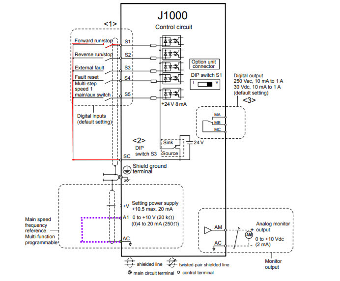
Controls Wiring:
-
S1 to SC For Auto Run
-
A1 and AC (0-10VDC or 4-20mA)

|
Partner Resolution (Distributor/Reseller)
 | |
|
|
Customer Service Resolution (Agent)
 | |
|
|
Engineering Resolution (Internal)
 | |
|
|
