Topic Description
 | |
|
AC reactors and/or a DC link choke (also known as a DC reactor) help reduce power line issues, lower harmonic distortion, and minimize the effects of the PWM output waveform associated with a VFD. A DC link choke (DC reactor) is connected to the DC bus while AC reactors can be used on the input or output side of a drive.
An input AC reactor and/ or DC link choke may be used for the following situations:
- To reduce harmonic current distortion and improve the power factor.
- To reduce the impact of transients and voltage spikes.
- When using a large capacity power supply transformer (over 600 kVA).
An output AC reactor may be used for the following situations:
|
Resolution
 | |
|
Input AC Reactor
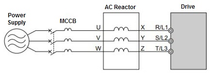
The image below shows a 3-phase, input AC reactor connected in series with the input of a drive.
- When using single-phase input, any two inputs/outputs of the AC reactor may be used but must stay consistent throughout. For example, use U - X and V - Y.

Output AC Reactor
The image below shows an output AC reactor connected in series with load side (motor) of the drive.
- A 3-phase motor must be used with Yaskawa's VFDs.
- Refer to the manufacturer for best placement of the AC reactor between the motor and the drive (i.e., near the VFD output or motor input terminals).

DC Link Choke (DC Reactor)
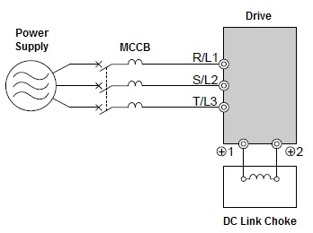
The image below shows a DC link choke (DC reactor) connected to the DC bus terminals on the drive.
- Larger model drives already have a DC link choke built in. For these drives, it is not possible to install an additional DC link choke. Refer to document: 1000 Series Drives with Built-In DC Bus Reactors (DC Link Choke)
- A DC link choke can be installed in smaller model drives. The DC terminals indicate whether or not a DC link choke is built into the drive.
- If the drive has +1 and +2 terminals, the drive does not have a built in DC link choke.
- If the drive has +1 and +3 terminals, the drive does have a built in DC link choke.
- When installing a DC link choke on smaller models, remove the factory jumper between +1 and +2 terminals. Wire the DC link choke to +1 and +2 as indicated in figure below.
- Install the DC link choke as close as possible to the drive.

|


