Topic Description
 | |
|
The static tests indicated below should be performed in the following scenarios:
- The VFD is blowing external fuses.
- The VFD is not turning on or won't turn on.
- The VFD is not powering up the digital operator.
- SC (short circuit), OC (overcurrent) or Output Phase Loss faults are present.
All the static checks below are conducted using the Diode Test Mode of a digital multimeter to determine if the input or output power circuits of the Variable Frequency Drive (VFD) are defective without having to take the VFD apart.
|
Resolution
| |
|
To perform the below static checks, locate the following terminals on the drive:
-
The p1 (+) and n1 (-) terminals are usually located on the left of the input terminals.
-
The R/L1, S/L2, T/L3 input and U/T1, V/T2, W/T3 output terminals.
-
The input fuses are located near the input terminals. (Covers will need to be removed to access the fuses)
Important steps before starting the below tests:
-
Disconnect the input and output wires connected to the VFD terminals.
-
Ensure the DC bus is completely discharged. Measure between the positive and negative bus with a DC voltmeter set to the highest scale. If the measured voltage is < 10Vdc, it is safe to work inside the Drive.
First Step:
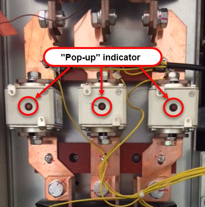
Check the input fuses by using (A) the "Pop-up" indicator or using (B) a multimeter set to resistance.
Note: Input fuses are not easily accessible on smaller drives.
| A. Visual inspect the "Pop-up" indicator: |
B. Turn the multimeter dial to resistance (Ω) and check across the input fuses.
Should read 0 Ω |
 |
 |
Second Step:
Turn the multimeter dial to Diode Test Mode as shown below:

2.a
-
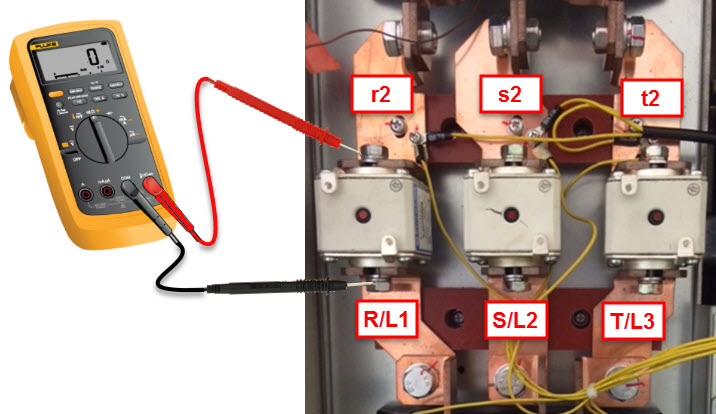
Take the positive multimeter lead and put it on each input terminal (R/L1, S/L2 and T/L3) of the VFD one at a time.
-
Take the negative multimeter lead and put it on each output terminal (U/T1, V/T2 and W/T3) of the VFD one at a time.
-
If a terminal is good, it should return with a OL (open) reading on the meter.
2.b
-
Take the positive multimeter lead and put it on each output terminal (U/T1, V/T2 and W/T3) of the VFD one at a time.
-
Take the negative multimeter lead and put it on each input terminal (R/L1, S/L2 and T/L3) of the VFD one at a time.
-
If a terminal is good, it should return with a OL (open) reading on the meter.
| Step 2 |
(+) Positive Multimeter Lead |
(-) Negative Multimeter Lead |
Multimeter Reading
(Diode Test Mode) |
Image |
| 2.a |
R/L1 Terminal |
U/T1 Terminal
V/T2 Terminal
W/T3 Terminal |
OL |
 |
| S/L2 Terminal |
U/T1 Terminal
V/T2 Terminal
W/T3 Terminal |
OL |
| T/L3 Terminal |
U/T1 Terminal
V/T2 Terminal
W/T3 Terminal |
OL |
| 2.b |
U/T1 Terminal
V/T2 Terminal
W/T3 Terminal |
R/L1 Terminal |
OL |
 |
U/T1 Terminal
V/T2 Terminal
W/T3 Terminal |
S/L2 Terminal |
OL |
U/T1 Terminal
V/T2 Terminal
W/T3 Terminal |
T/L3 Terminal |
OL |
Third Step:
Turn the multimeter dial to Diode Test Mode as shown below:
3. a
-
Take the positive multimeter lead and put it on the p1 terminal of the VFD.
-
Take the negative multimeter lead and put it on each input (R/L1, S/L2 and T/L3) and output (U/T1, V/T2 and W/T3) terminal of the VFD one at a time.
-
If a terminal is good, it should return with a OL (open) reading on the meter.
-
Take the positive multimeter lead and put it on each input (R/L1, S/L2 and T/L3) and output (U/T1, V/T2 and W/T3) terminal of the VFD one at a time.
-
Take the negative multimeter lead and put it on the p1 terminal of the VFD.
-
If a terminal is good, it should read a voltage drop from 0.299 to 0.675 vdc and consistent reading between all phases.
3. b
-
Take the positive multimeter lead and put it on the n1 terminal of the VFD.
-
Take the negative multimeter lead and put it on each input (R/L1, S/L2 and T/L3) and output (U/T1, V/T2 and W/T3) terminal of the VFD one at a time.
-
If a terminal is good, it should read a voltage drop from 0.299 to 0.675 vdc and consistent reading between all phases.
-
Take the positive multimeter lead and put it on the input (R/L1, S/L2 and T/L3) and output (U/T1, V/T2 and W/T3) terminal of the VFD one at a time.
-
Take the negative multimeter lead and put it on the n1 terminal of the VFD.
-
If a terminal is good, it should return with a OL (open) reading on the meter.
3. c
-
Take the positive multimeter lead and put it on the p1 terminal of the VFD.
-
Take the negative multimeter lead and put it on the n1 terminal of the VFD.
-
If a terminal is good, it should return with a OL (open) reading on the meter.
-
Take the positive multimeter lead and put it on the n1 terminal of the VFD.
-
Take the negative multimeter lead and put it on the p1 terminal of the VFD.
-
If a terminal is good, it should read a voltage drop from 0.299 to 0.675 vdc and consistent reading between all phases.
| Step 3 |
(+) Positive
Multimeter Lead |
(-) Negative
Multimeter Lead |
Multimeter Reading
(Diode Test Mode) |
Image |
| 3.a |
p1 Terminal |
R/L1 Terminal
S/L2 Terminal
T/L3 Terminal
U/T1 Terminal
V/T2 Terminal
W/T3 Terminal |
OL |
 |
R/L1 Terminal
S/L2 Terminal
T/L3 Terminal
U/T1 Terminal
V/T2 Terminal
W/T3 Terminal |
p1 Terminal |
0.299 ~ 0.675 vdc |
| 3.b |
n1 Terminal |
R/L1 Terminal
S/L2 Terminal
T/L3 Terminal
U/T1 Terminal
V/T2 Terminal
W/T3 Terminal |
0.299 ~ 0.675 vdc |
 |
R/L1 Terminal
S/L2 Terminal
T/L3 Terminal
U/T1 Terminal
V/T2 Terminal
W/T3 Terminal |
n1 Terminal |
OL |
| 3.c |
p1 Terminal |
n1 Terminal |
OL |
 |
| n1 Terminal |
p1 Terminal |
0.299 ~ 0.675 vdc |
Fourth Step:
Turn the multimeter dial to Diode Test Mode as shown below:
-
Take the positive multimeter lead and put it on each input (R/L1, S/L2 and T/L3) and output (U/T1, V/T2 and W/T3) terminal of the VFD one at a time
-
Take the negative multimeter lead and put it on ground of the VFD.
| Step 4 |
(+) Positive
Multimeter Lead |
(-) Negative
Multimeter Lead |
Multimeter Reading
(Diode Test Mode) |
Image |
| 4 |
R/L1 Terminal
S/L2 Terminal
T/L3 Terminal
U/T1 Terminal
V/T2 Terminal
W/T3 Terminal |
 |
OL |
 |
|
All Applications
| |
|
| Advanced Random Rotary Knife with Cam Blend,
Air Compressor,
Blister pack Thermoformer,
Cartoner,
Centrifuge,
Conveyor,
Crane/Hoist,
Dynamometer,
Elevators and Escalators,
Extrusion,
Fans/Blowers,
Feed To Length,
General Machinery,
HVAC,
Irrigation,
Labeler,
Laundry,
Linear Flying Shear,
Machine Tool,
Mixer,
Other,
Packaging,
Palletizer,
Precision Grinding,
Pump,
Punch Press,
Rotary Knife,
Rotary Placer,
Rotary Table Indexer,
Screw Feeder,
Semiconductor,
Solar Cell Tabbing and Bussing,
Solar - Textured Etching,
Synch-Belt,
Textile,
Winding,
|