Topic Description
 | |
|
Both a damper actuator and a damper end switch can be directly wire to a HV600 or Z1000 drive. The damper actuator can either utilize the drive's internal 24 Vdc (max 150mA) power supply or use an external power supply (AC or DC type). The damper end switch is typically an output contact from the actuator and gets wired to the digital input terminals on the drive.
|
Resolution
| |
|
When a RUN command is issued (typically on S1/SN), a digital output (M1/M2 for example) will close supplying a damper actuator with power to open a damper. Once the damper is fully open, a damper end switch will close a contact wired to a digital input terminal (Sx/SN) on the drive. When the drive receives the damper end switch command, the drive will start the motor.
- If the RUN command is removed, the digital output (M1/M2) will open removing power to the damper actuator.
- If the damper end switch is not closed but the drive is receiving the RUN command, the message "INTLK" (Interlock Open) will be displayed.
Programming
- Set H1-xx (Multi-Function Digital Input Terminal Sx) = B2 (BAS Interlock).
-
Example: Set H1-03 = B2 if S3 is being used (see wiring diagram below).
- Set H2-xx (Multi-Function Digital Output) = B2 (BAS Interlock Relay Contact).
-
Example: Set H2-01 = B2 if M1/M2 are being used (see wiring diagram below).
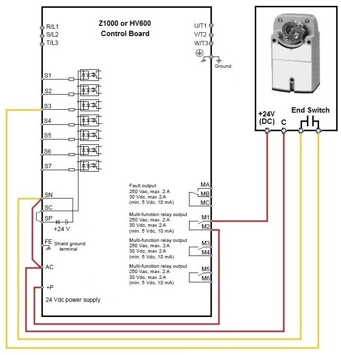
Wiring Using the Drive's Internal Power Supply (24VDC only)
- Jumper SN and AC.
-
Note: This is not necessary on HV600 drives.
- Connect the common from damper to terminal AC on drive.
- Connect positive 24V from damper to terminal M1 on drive.
- Connect terminal M2 on drive to terminal +P on drive.
- Connect damper end switch to terminals S3 and SN on drive.
Note: Other digital inputs Sx/SN or digital outputs Mx/Mx may have been used instead.
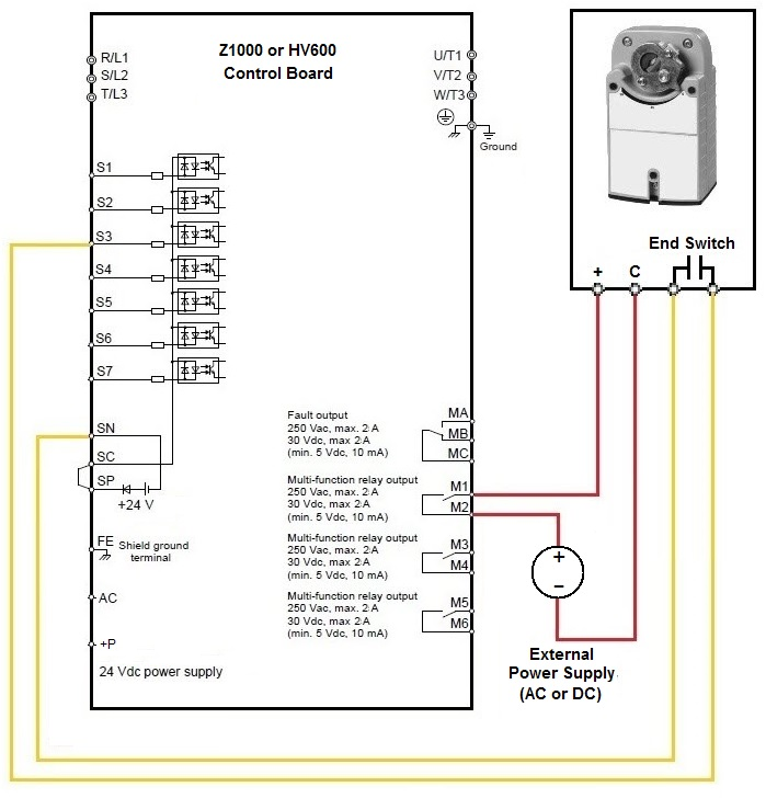
Wiring Using an External Power Supply (AC or DC)
- Connect the common from damper to common on external power supply.
- Connect + from damper to terminal M1 on drive.
- Connect terminal M2 on drive to the + on the power supply.
- Connect damper end switch to terminals S3 and SN on drive.
Note: Other digital inputs Sx/SN or digital outputs Mx/Mx may have been used instead.
| Using the Drive's Internal Power Supply (24VDC Only) |
Using an External Power Supply (AC or DC) |
 |
 |
Note:
-
The 24 Vdc power supply is rated for 150mA max (Z1000) or 700mA max (HV600).
-
The digital output terminals are rated for 250 Vac max at 2 A or 30 Vdc max at 2A.
|