Topic Description
 | |
|
In many HVAC and fan applications, actuators are used to open and close dampers depending on the air flow. Often at times, it may be desired to use a damper end switch with a GA800, GA500, A1000, or V1000 drive. The following process allows for a (BAS) damper interlock circuit when a RUN command is present.
- A RUN command is issued to the drive (uses the Drive Enable function).
- A digital output (status of Drive Enable) will close a set of contacts and send a signal to the damper motor to open the damper.
- Once the damper reaches its end point, a set of damper contacts will close, sending a signal to the drive to start.
|
Resolution
| |
|
Follow the steps below to setup a damper interlock circuit on a GA800, GA500, A1000, or V1000 drive.
Programming
- Set parameter H1-0x = 6A (Drive Enable). This will correspond to the digital input terminal Sx used for the RUN command.
-
Example: If using terminal S3, set parameter H1-03 = 6A.
- Set parameter H2-0x = 38 (Drive Enable). This will correspond to the digital output terminals Mx and My used for the damper motor.
-
Example (GA800/A1000): If using terminals M1/M2, set parameter H2-01 = 38.
-
Example (GA500/V1000): If using terminals MA/MC, set parameter H2-01 = 38.
Wiring
- Wire the RUN command to terminals Sx and SN / SC. This is the digital input programmed for Drive Enable (H1-0x = 6A).
- Wire the damper end switch to terminals S1 and SN / SC.
- Wire the damper motor to terminals Mx and My. This is the digital output programmed for Drive Enable (H2-0x = 38)
See below for example wiring diagrams:
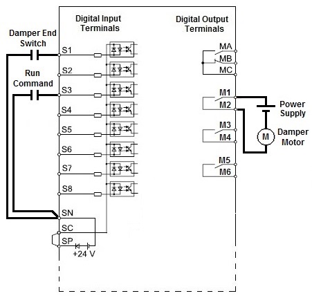
| A1000 and GA800 Drives |
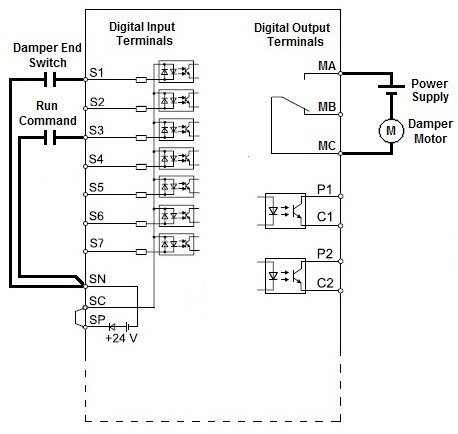
GA500 |
V1000 |
 |
 |
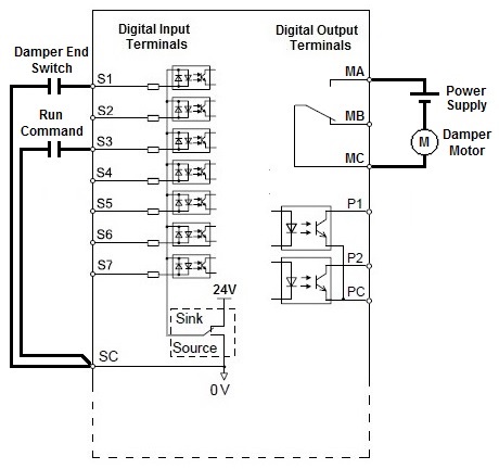 |
Note: The digital output terminals M1/M2 and MA/MC are rated for 30VDC or 250VAC, max 1A.
|