Troubleshooting an oV (DC Bus Overvoltage) Fault when Using a CDBR-xxxxD Dynamic Braking Unit
Topic Description

An oV (DC Bus Overvoltage) fault is triggered when the drive's DC bus voltage rises higher than the overvoltage trip point. A CDBR (Dynamic Braking) unit paired with a resistor(s), is used to help decelerate and bring the motor to a smooth stop to prevent a fault such as an oV. If an oV fault is occurring when using a CDBR unit, an issue may be present with a system component or the CDBR unit may not be sized correctly for the application. The oV fault trip point is approximately:

  • 410 VDC for a 200 V class drive
  • 820 VDC for a 400 V class drive
  • 1040 VDC for a 600 V class drive

Resolution

Follow the steps below when troubleshooting an oV (DC Bus Overvoltage) fault when using a CDBR-xxxxD Dynamic Braking Unit:

  1. Verify the parameters are set correctly on the drive when using dynamic braking. Refer to document: Programming when Installing a Dynamic Braking Option.
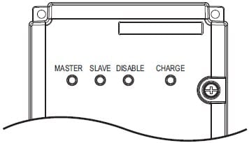
  2. With power applied to the drive, view the LEDs on the CDBR Braking Unit to ensure the braking unit is in working condition. The DISABLE LED must be OFF, the CHARGE LED must be ON and either the MASTER or SLAVE LED must also be ON.

     
    LED Color Lit Off
    MASTER Green CDBR is functioning as Master CDBR is functioning as Slave
    SLAVE Green CDBR is functioning as Slave CDBR is functioning as Master
    DISABLE Red Fault has occurred Normal operation
    CHARGE Red CDBR is powered on -
     
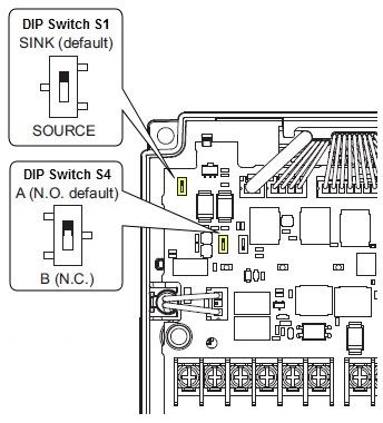
  3. Verify the DIP switch settings for S1 and S4.
    • DIP switch S1 is used to select SINK or SOURCE mode for the SB to SC Enable input.
      • If S1 is set to SINK (factory setting), it is using internal 24Vdc.
      • If S1 is set to SOURCE, an external 24Vdc (Class 2) power supply is required.
    • DIP switch S4 is used to select the contact type to either Normally Open (N.O.) or Normally Closed (N.C.).
      • If S4 is set to N.O. (factory setting) and the SB to SC terminals are OPEN, the Dynamic Braking unit is automatically enabled.
      • If S4 is set to N.C. and the SB to SC terminals are CLOSED, the Dynamic Braking unit must be remotely enable by a switch across terminals SB to SC.

         
        Refer to the table below for the DIP switches S1 and S4 details.
        DIP Switch S1
        SINK/SOURCE
        DIP Switch S4-SB/SC
        Terminals N.O./N.C.
        SB-SC Enable Input CDBR Status
        SINK A Open Enabled
        SINK A Close Disabled
        SINK B Open Disabled
        SINK B Close Enabled
        SOURCE A 0V Input Enabled
        SOURCE A 24V Input Disabled
        SOURCE B 0V Input Disabled
        SOURCE B 24V Input Enabled
         
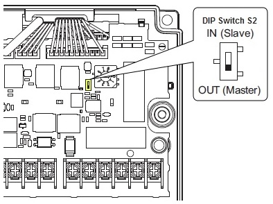
  4. Verify the DIP switch setting for S2. The default setting of DIP switch S2 is OUT (Master). Change the switch position only when operating the unit as a slave device.
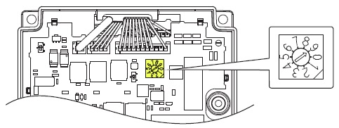
  5. Check the Braking Start Voltage rotary switch S3. Set the Voltage Activation Level rotary switch S3 to match the power supply of the main circuit. The default rotary switch S3 setting is 9.

     
    Refer to the table below for the S3 rotary switch position and braking start voltage details.
    Rotary Switch S3 Setting 200V Class 400V Class 600V Class
    Input
    Voltage (V)
    Braking Activation
    Voltage (V)
    (PN Bus Voltage)
    Input
    Voltage (V)
    Braking Activation
    Voltage (V)
    (PN Bus Voltage)
    Input
    Voltage (V)
    Braking Activation
    Voltage (V)
    (PN Bus Voltage)
    0 160 270 (TYP) 380 630 (TYP) 500 825 (TYP)
    1 170 282 (TYP) 390 644 (TYP) 505 839 (TYP)
    2 175 294 (TYP) 400 659 (TYP) 515 853 (TYP)
    3 185 307 (TYP) 405 673 (TYP) 525 867 (TYP)
    4 190 319 (TYP) 415 688 (TYP) 530 881 (TYP)
    5 200 331 (TYP) 425 702 (TYP) 540 894 (TYP)
    6 208 343 (TYP) 430 717 (TYP) 550 908 (TYP)
    7 215 356 (TYP) 440 731 (TYP) 555 922 (TYP)
    8 220 368 (TYP) 450 746 (TYP) 565 936 (TYP)
    9 <1> 230 380 (TYP) 460 760 (TYP) 575 950 (TYP)
      <1> Default setting
     
  6. Check the wiring between the drive, resistor, and braking unit.
  7. Check the braking resistor(s) following the steps below:
    1. Remove power to the drive. 
    2. Disconnect the resistor(s) from the circuit and determine the rated value (ohms) of the resistor(s) which is usually stamped or labeled on the resistor itself.
    3. Visually inspect the resistor(s) for cracks, defects, etc.
    4. Use a multimeter to measuring the resistance.
    5. Compare the resistance readings (ohms) to the value stamped on the resistor.
    6. If the resistance measured is significantly different from rated value of the resistor, replace the resistor.

Related Documents
Braking Activation Level for a CDBR-D Braking Unit and Drives with Built-in Dynamic Braking
Connecting a Braking Resistor and CDBR Braking Unit to a Drive (Larger Models)
Connecting a Braking Resistor or CDBR Braking Unit to a Drive (Smaller Models)
Dynamic Braking Module (CDBR) and Resistor Combinations and Wiring Arranged by System Voltage, Motor HP and Duty

Product Types
GA800, GA800 Configured, A1000, A1000 Configured, G5, F7, F7C Configured, L1000, L7, V1000, V1000-4X, V7,
All Applications
Advanced Random Rotary Knife with Cam Blend, Air Compressor, Blister pack Thermoformer, Cartoner, Centrifuge, Conveyor, Crane/Hoist, Dynamometer, Elevators and Escalators, Extrusion, Fans/Blowers, Feed To Length, General Machinery, HVAC, Irrigation, Labeler, Laundry, Linear Flying Shear, Machine Tool, Mixer, Other, Packaging, Palletizer, Precision Grinding, Pump, Punch Press, Rotary Knife, Rotary Placer, Rotary Table Indexer, Screw Feeder, Semiconductor, Solar Cell Tabbing and Bussing, Solar - Textured Etching, Synch-Belt, Textile, Winding,
Option Types
CDBR Unit, Dynamic Braking,
Last Modified Date: 07-22-2024ID: 11110