Setting Multi-Step Speed References
Topic Description

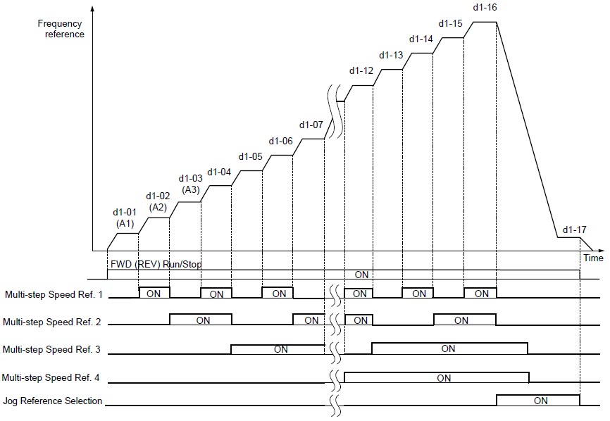
The Multi-Step function allows the user to switch between up to 17 preset frequency references during run (including the Jog reference) through the digital input terminals (H1-0x parameters). The drive uses the acceleration and deceleration times that have been selected when switching between each frequency reference. An example for this function would be using a multi-position switch to select between preset speeds (frequency references). 

Note:

  • Not all parameter and functions will be available in all drive models.
  • The Jog frequency overrides all other frequency references and must be selected by a separate digital input.
  • The multi-speed references 1, 2, and 3 can be provided by analog inputs.

Resolution

To use the Multi-Step function, set the digital input H1-0x parameters to 3, 4, 5, and/or 32 (see table below). To assign the Jog reference to a digital input, set H1-0x = 6. Then, program the Frequency References (d1-01 thru d1-17) accordingly. 

Digital Input Setting Function
H1-0x = 3 Mult-Step Reference 1
H1-0x = 4 Mult-Step Reference 2
H1-0x = 5 Mult-Step Reference 3
H1-0x = 32 Mult-Step Reference 4
H1-0x = 6 Jog Reference

Use the table below to deternine which frequency reference the drive will look at when using the Multi-Step function.

Digital Inputs      
Multi-Step Inputs Jog Input Frequency Reference
H1-0x = 3 H1-0x = 4 H1-0x = 5 H1-0x = 32 H1-0x = 6 b1-01 = 0 (keypad) b1-01 = 1 (analog input) Name
Open Open Open Open Open d1-01 Analog input (H3-xx = 0) <1> Frequency Reference 1
Closed Open Open Open Open Analog input (H3-xx = 2) or d1-02 <2> Frequency Reference 2
Open Closed Open Open Open Analog input (H3-xx = 3) or d1-03 <3> Frequency Reference 3
Closed Closed Open Open Open d1-04 Frequency Reference 4
Open Open Closed Open Open d1-05 Frequency Reference 5
Closed Open Closed Open Open d1-06 Frequency Reference 6
Open Closed Closed Open Open d1-07 Frequency Reference 7
Closed Closed Closed Open Open d1-08 Frequency Reference 8
Open Open Open Closed Open d1-09 Frequency Reference 9
Closed Open Open Closed Open d1-10 Frequency Reference 10
Open Closed Open Closed Open d1-11 Frequency Reference 11
Closed Closed Open Closed Open d1-12 Frequency Reference 12
Open Open Closed Closed Open d1-13 Frequency Reference 13
Closed Open Closed Closed Open d1-14 Frequency Reference 14
Open Closed Closed Closed Open d1-15 Frequency Reference 15
Closed Closed Closed Closed Open d1-16 Frequency Reference 16
N/A N/A N/A N/A Closed d1-17 Jog Reference

Note:

  • <1> Analog inputs are programmed with parameters H3-02 (A1), H3-06 (A3), and H3-10 (A2).
  • <2> Analog inputs programmed for "2" Aux Frequency Reference 1 takes priority over d1-02 (Frequency Reference 2). If no analog inputs are set for "2", then d1-02 will be the frequency reference.
  • <3> Analog inputs programmed for "3" Aux Frequency Reference 2 takes priority over d1-03 (Frequency Reference 3). If no analog inputs are set for "3", then d1-03 will be the frequency reference.
  • Monitor U1-10 can be used as a troubleshooting tool to see which digital inputs are active. Refer to document: Testing Digital Input Signals in Sinking Mode.

The frequency reference timing diagram below displays how the drive can use the different frequency references to run at different preset speeds.

Example

An example of utilizing the Multi-Step function is to have a 3-position switch for 3 different preset speeds. In this situation, no analog input is present and the frequency reference (speed) is determined by which digital input is active (closed). Programming will include the following:

  • b1-01 = 0 (Frequency Reference = Digital Operator)
  • d1-02 = Speed 1 (Frequency Reference 2)
  • d1-03 = Speed 2 (Frequency Reference 3)
  • d1-05 = Speed 3 (Frequency Reference 5)
  • H1-05 = 3 (Terminal S5 = Multi-Step Input 1) - Default
  • H1-06 = 4 (Terminal S6 = Multi-Step Input 2) - Default
  • H1-07 = 5 (Terminal S7 = Multi-Step Input 3)

Note: If the switch contacts are open at any point, parameter d1-01 (Frequency Reference 1) will become the frequency reference (speed). 

Digital Inputs    
Multi-Step Inputs Frequency Reference
H1-05 = 3 H1-06 = 4 H1-07 = 5 b1-01 = 0 (keypad) Name
Open Open Open d1-01 Frequency Reference 1
Closed Open Open d1-02 Frequency Reference 2
Open Closed Open d1-03 Frequency Reference 3
Closed Closed Open d1-04 Frequency Reference 4
Open Open Closed d1-05 Frequency Reference 5

Related Documents
Changing the Frequency Reference from the Keypad on a V1000, J1000, or GA500 Drive
Multi-Step Speed References on E7L or E7N Bypass Units (with Control PCB UTC000044 or UTC0000510)
Switching Between A1, A2, or A3 Analog Inputs for Frequency Reference
Switching Between Two Analog Input References
Z1B or P1B Bypass Multi-step Speed Reference

Product Types
GA800, GA800 Configured, GA500, HV600, HV600 Bypass, HV600 Configured, 1000 Series,
All Applications
Advanced Random Rotary Knife with Cam Blend, Air Compressor, Blister pack Thermoformer, Cartoner, Centrifuge, Conveyor, Crane/Hoist, Dynamometer, Elevators and Escalators, Extrusion, Fans/Blowers, Feed To Length, General Machinery, HVAC, Irrigation, Labeler, Laundry, Linear Flying Shear, Machine Tool, Mixer, Other, Packaging, Palletizer, Precision Grinding, Pump, Punch Press, Rotary Knife, Rotary Placer, Rotary Table Indexer, Screw Feeder, Semiconductor, Solar Cell Tabbing and Bussing, Solar - Textured Etching, Synch-Belt, Textile, Winding,
Last Modified Date: 11-21-2023ID: 11011