Setting Up a Differential PI Feedback Loop on 1000 series and GA800 drives (Non-iQpump Drives)
Topic Description

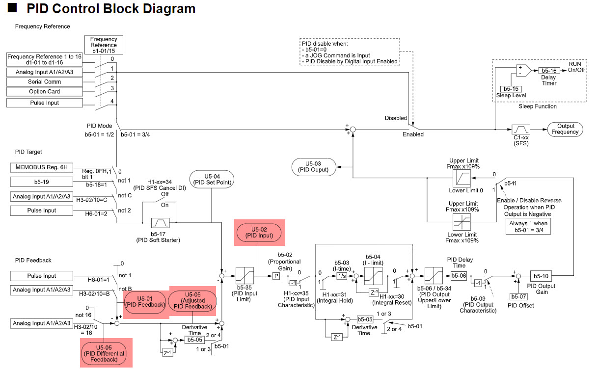
Most Yaskawa drives are capable of differential feedback, which requires two transducers. The drive essentially takes the differential feedback value, which is PID Adjusted Feedback (U5-06), and incorporates it into the PID loop.

This kind of application could be used for buildings that require a certain differential pressure between two rooms, to prevent issues with doors from opening and closing. One transducer would be measuring the static pressure of a room, while the secondary transducer would measure the pressure of an adjacent room. The drive will use the differential feedback value to maintain the desired differential pressure between the two rooms.

Note: 

  • Both transducers MUST be of the same type with the same scaling
  • The PID Adjusted Feedback (U5-06) = PID Feedback (U5-01) - PID Differential Feedback (U5-05).
  • The PID Input (U5-02), shows the change between the PID setpointPID feedback and PID Differential Feedback (the quantity of PID input) as a percentage of the maximum output frequency. 
    • U5-02 = PID setpoint PID feedback Differential Feedback. If this reads 0 the drive will not run. Anything but a 0 the drive will run. 
  • The differential feedback function is automatically enabled when a differential feedback soure is assigned to an analog input (H3-0x = 16).
  • The differential feedback function is ONLY available for A1000, V1000, V1000-4X, P1000, Z1000, Z1000U and GA800 drives.

Resolution

Use the following steps to setup a PID loop with differential feedback:

  1. Set b5-01 (PI function setting) = 1 (Enable PID)
  2. Set b5-18 (PI setpoint selection) = 1 (Enable)
  3. Set b5-20 (PI setpoint scaling) = 3 (User-set from b5-38 and b5-39)
  4. Set b5-38 (PI setpoint user display) = Desired scaling value with decimal placement 
  5. Set b5-39 (PI setpoint display digits) = Desired decimal places of b5-38
  6. Set b5-19 (PI setpoint value percentage of PI transducer range) = Desired Setpoint to maintain 
      Note: Must be set after setting b5-20, b5-38 and b5-39
  7. Set b5-09 (PI Output Level Selection) = 0 (Direct acting, usually used for building pressure applications) or 1 (Reverse Acting, usually used for level control applications)
  8. Choose two analog inputs for each transducer
    1. Set H3-0x = B (PID Feedback)  For example: Using A1, set H3-02 = B
    2. Set H3-0x = 16 (PID Differential Feedback)  For example: Using A2, set H3-10 = 16
    3. Set H3-01, H3-09, H3-05 accordingly for either 0-10V or 4-20mA input
    4. Set any DIP switches or jumpers accordingly for either voltage or current input
  9. b5-46 (PI Setpoint Monitor Units) = Desired units 
  10. b5-15 (PI Sleep Function Start Level) = Desired frequency to go to sleep. (If desired to go to sleep)
  11. b5-16 (PI Sleep Delay Time) = Desired amount of time drive waits before entering/exiting sleep mode

Related Documents
Basic Setup for a PID Loop on a GA800, GA500, and 1000 Series Drives
Example of a basic setup for Temperature Control PID Loop on a 1000 series drive (Non-iQpump drives)
Using Multiple PID Setpoints in 1000 Series Drives

Product Types
GA800, A1000, A1000 Configured, P1000, P1000 Bypass, P1000 Configured, V1000, V1000-4X, Z1000, Z1000 Configured,
All Applications
Advanced Random Rotary Knife with Cam Blend, Air Compressor, Blister pack Thermoformer, Cartoner, Centrifuge, Conveyor, Crane/Hoist, Dynamometer, Elevators and Escalators, Extrusion, Fans/Blowers, Feed To Length, General Machinery, HVAC, Irrigation, Labeler, Laundry, Linear Flying Shear, Machine Tool, Mixer, Other, Packaging, Palletizer, Precision Grinding, Pump, Punch Press, Rotary Knife, Rotary Placer, Rotary Table Indexer, Screw Feeder, Semiconductor, Solar Cell Tabbing and Bussing, Solar - Textured Etching, Synch-Belt, Textile, Winding,
Last Modified Date: 07-22-2024ID: 12467